



# Getting the Most Out of Vision-Guided Bin Picking in Manufacturing
Bin picking has been on the horizon of factory automation for years, and the technology has finally reached a point where it can deliver real results on production floors. But deploying a vision-guided picking system successfully involves far more than connecting a camera to a robot arm. The decisions that separate a project that works from one that works reliably happen during design, planning, and long after installation.
This article walks through what actually matters when bringing bin picking into a manufacturing environment—covering everything from part evaluation to cycle time expectations, from cell layout to ongoing maintenance.
—
## When Should You Consider Bin Picking?
Bin picking solves a specific problem: parts arrive in a container with no fixed arrangement, or they arrive with positional variations that require visual guidance before the robot can pick them. The moment your parts come in a predictable pattern, a fixed sequence of robot motions is faster, cheaper, and more reliable.
Before committing to bin picking, consider whether simpler alternatives exist:
– **Fixed input trays** eliminate randomness before parts even reach your workstation. If your upstream process can deliver parts in a consistent orientation, that’s almost always the better path.
– **Bowl feeders** work well for high-volume, low-variety scenarios involving small, sturdy parts. They’re fast and proven, but they don’t handle much diversity.
– **Manual loading** may still make sense if the loading step is a small fraction of the total cycle time. Automating a 5-second load step when the processing step takes 60 seconds rarely pencils out.
If parts are hard to grip or recognize even at the planning stage, production will amplify those difficulties. Take a skeptical look at cycle time goals, too. A 4-second pickup works for simple parts but falls apart when precise finger positioning is required.
—
## What a Complete System Actually Looks Like
A vision-guided picking system is more than a camera and a robot. A fully functional cell includes:
– A robot arm (standard or collaborative)
– A 3D vision camera
– A controller with processing capabilities for scene analysis and pick planning
– An end-effector (suction cups or gripper fingers)
– Lighting fixtures
– Support structures and source/destination containers
– An electrical panel and safety components
Each of these elements affects performance, and every one deserves attention during planning.
## Setting Realistic Expectations
### On Performance
In day-to-day production, expect pickup success rates between 98 and 99.9 percent and cycle times ranging from roughly 4 to 8 seconds. Lab demonstrations rarely stress-test cycle times, so actual production performance often exceeds what a demo shows. Success rates also tend to climb once the system has been tuned for real-world conditions.
### On Timeline
Expect about one to two weeks of preparation work off-site—model training, application logic development, camera and controller integration, and initial tuning. On-site installation and ramp-up typically adds a few days to two weeks. A first successful pick within an afternoon is realistic, but reaching steady, reliable production takes longer than most people assume.
### On Budget
Engineering time is where surprises hide. Mechanical design, electrical design, fabrication lead time, and on-site installation all need to be accounted for. Installation and tuning labor is the line item most teams underestimate, especially for complex applications.
—
## Evaluating Your Parts and Containers
The characteristics of the parts you’re picking and the bins they arrive in shape what’s possible more than any software tuning decision.
**Parts that are straightforward to pick:**
– Matte surfaces that don’t reflect light or create transparency issues
– Parts large enough relative to the container to be located reliably
– Flat, smooth surfaces that suction cups can seal against
– Destinations where precise placement isn’t critical
**Parts that present challenges:**
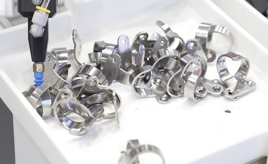
– Shiny or reflective metallic surfaces
– Transparent or translucent materials
– Dark objects that absorb light
– Irregular geometries that are hard to grip with standard suction cups or parallel grippers
**Density matters, too.** A bin packed with many small parts is harder to work with than one holding a few large ones—even if the total volume is the same. The ratio of part size to container size is the key metric.
Weight difficulty depends on the gripper, not just the part itself. A large, heavy box picked with a properly sized suction cup can be easy, while a small, dense, oddly shaped part may be very difficult with standard tooling.
Fully transparent parts like glass components are generally not well-suited for bin picking. Translucent parts are harder but sometimes workable. Feasibility testing with real hardware is the fastest way to find out where your application stands.
—
## How the Vision System Works
A standard 2D camera captures width and height but has no depth information—insufficient for directing a robot to reach into three-dimensional space. A 3D camera adds depth, giving the system the spatial data it needs to locate a part and plan a collision-free pick.
Most 3D vision systems used in manufacturing employ stereo imaging combined with intelligent depth processing. Camera models are available for short-range, tabletop, and long-range applications, and selecting the right one for your working distance and container dimensions is an early, important decision.
### Lighting and Calibration
Lighting is the most common source of trouble in production environments. Overexposed regions, glare from reflective parts, underexposed shadow areas in deep bins—each can cause failures that don’t appear during lab testing. Designing the cell with lighting contingencies upfront prevents headaches later.
Two types of calibration matter: the internal calibration of the camera itself (done at the factory) and the alignment between the camera and the robot (done during installation). Field errors in calibration almost always come from incorrect reference frame definitions or insufficient coverage during the calibration poses.
As a general guideline, expect end-to-end system accuracy of approximately 0.5 percent of the container’s dimension. A 10-centimeter tray yields roughly 0.5 millimeter of accuracy; an 80-centimeter tray yields about 4 millimeters. Build your placement requirements around realistic accuracy, not theoretical best-case numbers.
—
## Cell Design: Choices That Compound
### Camera Placement
Mounting the camera in a fixed position above the bin is the default choice for most applications. The ideal height depends on bin size, part dimensions, and the robot’s reach.
An in-hand camera, mounted on the robot wrist, is worth considering when multiple bins need coverage or when parts are small and need close inspection. The trade-off is speed: an in-hand camera adds about 1 to 2 seconds per cycle because the robot must pause to capture each image. A fixed camera allows the robot to keep moving and grab images between picks.
### Gripper Selection
Suction cups are the go-to choice when the part has a large, flat, clean surface. They’re mechanically simpler and faster because orientation relative to the part is less critical.
A two-finger parallel gripper is the most robust alternative when suction isn’t viable. More complex gripper designs exist for unusual geometries, but they add mechanical complexity and potential points of failure. Finger grippers generally add 1 to 2 seconds per cycle compared to suction cups.
### Robot Type
Standard industrial robots are 3 to 4 seconds faster than collaborative robots, which are deliberately speed-limited for safety. The speed difference compounds with camera and gripper choices, so the full system configuration should be evaluated together.
—
## The Design Principle That Makes Everything Easier
When a challenge can be solved either mechanically or with software, choose the mechanical solution. Software is flexible and powerful, but it is rarely as dependable or as cost-effective as getting the physical setup right.
Integration work—connecting the robot, controller, PLC, and other components—is where most project delays originate. Outdated or proprietary software interfaces, poor network configuration, and unanticipated communication issues between cell components can derail timelines. Wired connections using modern ethernet standards are strongly preferred over WiFi for cell communication.
—
## What Breaks—and How to Prevent It
The failures seen most consistently in deployed systems fall into three categories:
1. **Mechanical wear** on grippers, cables, and connections loosening from repeated motion
2. **Calibration drift** caused by vibration or physical shock to the camera mount
3. **Environmental interference** like unexpected light sources, dust, or debris in the bin
Calibration drift is especially tricky because it doesn’t cause sudden failures. Instead, it produces a slow, gradual decline in pick accuracy or intermittent misses that are hard to reproduce. If miss rates creep upward over weeks or months, recalibrate the camera before investigating software issues.
One real-world example: a cleaning crew wiped the camera housing, shifting it by less than 0.1 degree. Because the camera was mounted more than a meter above the bin, this created roughly 1 millimeter of positioning error, causing failures about once every few hundred cycles. The robot was placing laser lenses into coating jigs with extremely tight clearance, so the errors were costly.
The takeaway: write a clear standard operating procedure that specifies what personnel can and cannot do near the camera, and include camera inspections in routine maintenance checklists.
—
## Maintenance That Prevents Pain
Three practices consistently separate reliable systems from problematic ones:
– A clear, documented cell maintenance SOP
– Quarterly preventive maintenance visits
– Multi-day stress testing before the system goes live
None of these are revolutionary ideas, but they are skipped more often than they should be when project timelines feel tight.
Over the life of a system, three metrics define long-term success:
– Sustained pick success rate
– Downtime spent debugging and fixing issues
– Downtime required when adding new product types
The third metric is often overlooked in initial planning but becomes significant as the system ages. Solutions that require vendor involvement or new CAD data for every product change create ongoing dependencies that erode return on investment over time.
—
## Financial Justification
A simple starting rule: if the system can free up one worker across two shifts per day, it’s likely worth exploring further. The specific economics depend on part value—high-value parts may justify a system with only a few hundred picks per day, while low-value items like small molded plastic components might require thousands of picks to make the case.
In the U.S. manufacturing market, a return on investment of two to four years is a reasonable expectation for a well-scoped project. Applications with difficult parts, tight cycle time requirements, or frequent product changes tend toward the longer end of that range.
Hardware costs are straightforward to quote. The engineering effort required to tune a complex system to stable production is harder to predict and is where budget surprises most commonly arise.
—
## Frequently Asked Questions
**Q: How long does it take to set up a new product type on a bin picking system?**
A: This varies widely by system. Some platforms allow new workpieces to be trained in minutes, while others may require CAD data submission or software updates that take days. The difference matters significantly for operations that handle many product types.
**Q: Can bin picking handle thousands of different parts?**
A: It can, but warehouse-style applications with thousands of varying shapes, materials, and weights represent some of the most challenging automation problems in the industry. They require more engineering effort and tuning time than single-product or low-variety manufacturing applications.
**Q: What success rate should I plan for?**
A: A 98 to 99.9 percent pickup success rate is what well-tuned production cells typically achieve. Designing a system around a theoretical 100 percent success rate introduces unnecessary complexity and cost.
**Q: Do I need to be a vision engineer to deploy bin picking?**
A: No, but having a working understanding of how 3D vision works helps avoid common mistakes during planning and integration. The key concepts—camera types, calibration, lighting, and accuracy expectations—are accessible to non-specialists.
**Q: What’s the hardest part of a bin picking project?**
A: Integration and on-site tuning are where most delays originate. The mechanical and electrical scope of the cell, network configuration, and collaboration between vendor and customer all play significant roles. Having a dedicated point of contact on the customer side who understands both the production process and the technology makes a substantial difference.
**Q: Can bin picking work with reflective or transparent parts?**
A: Reflective metallic surfaces, transparent materials, and dark light-absorbing parts all present challenges. Feasibility testing with real parts is the best way to determine viability. Fully transparent parts are generally not suitable, while translucent parts may be workable depending on the application.
**Q: How accurate does a bin picking system need to be?**
A: End-to-end accuracy is typically around 0.5 percent of the container dimension. Place your placement tolerances around realistic accuracy figures rather than theoretical best-case numbers.
—
## Conclusion
Vision-guided bin picking is a mature, production-ready technology that can deliver significant value in manufacturing environments. But its success depends on realistic expectations, thorough planning, and attention to the mechanical, electrical, and operational details that don’t always make it into vendor demonstrations.
The best projects start with honest evaluation of whether bin picking is the right tool, move through careful part and container assessment, and continue with thoughtful cell design, calibration, and maintenance planning long after installation. When the physical setup is prioritized over software workarounds, when integration challenges are budgeted for, and when the right people are empowered to troubleshoot collaboratively, the results speak for themselves.
Getting the first pick right is just the beginning. Sustained, reliable performance over months and years is what turns a technology investment into a lasting competitive advantage.
Thank you for reading
