



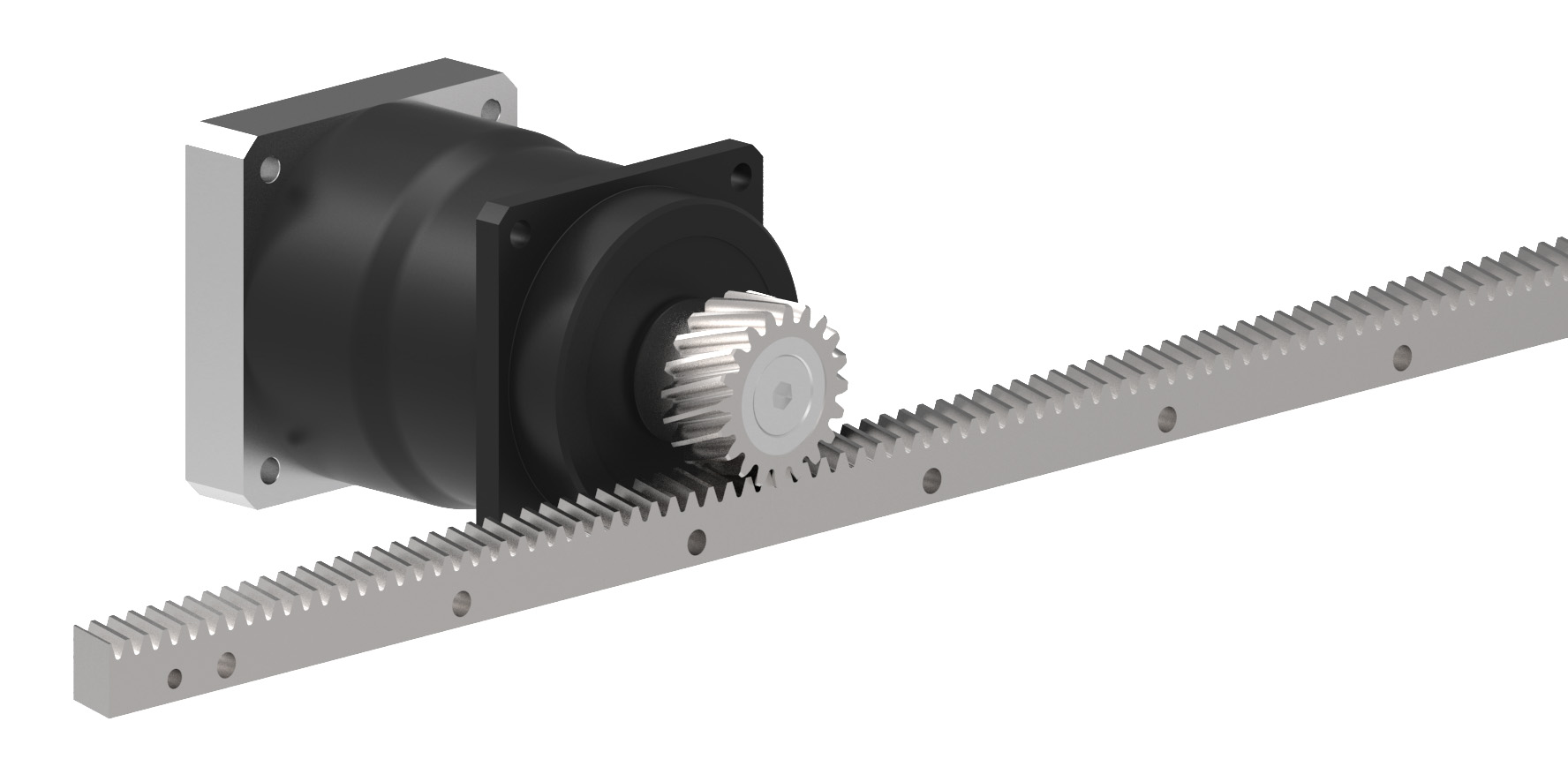
Consider the humble scissor jack stored in a vehicle’s trunk. When you rotate the crank, the spinning motion is transformed into a straight, linear lift. This mechanical concept is the foundation of rack and pinion systems. In such a setup, the pinion acts as the rotating gear that receives the rotational input, while the rack serves as a long, toothed bar that the pinion meshes with to produce linear movement. Depending on the design, either the rack travels back and forth while the pinion remains stationary, or the rack is fixed and the attached mechanism moves along its length.
Selecting the appropriate mechanism for a linear motion application is a critical decision, as an incorrect choice can severely compromise both system performance and budget. Engineers often face a balancing act: choosing a system that is too small risks mechanical failure, while an oversized system can create spatial constraints and inflate costs unnecessarily.
The sizing process typically begins by identifying the primary requirement—either the necessary feed force or the target speed—and then working backward from there. When feed force is the priority, the rack must be robust enough to transmit the load, and the pinion must be properly matched to the driving motor or gearbox. Conversely, when speed is the main concern, the components are selected to ensure the system can reach the desired velocity based on the motor’s input speed.
In some cases, the process runs in reverse. If a motor has already been chosen, engineers size the rack and pinion based on the motor’s output speed and the required positioning accuracy. Applications demanding high precision often benefit from a higher-quality rack and a smaller pinion. A smaller pinion minimizes the impact of any rotational backlash or error from the gearbox, preventing that slop from being amplified across the linear travel. A smaller pinion also transmits torque more efficiently, requiring less input from the motor and allowing for smaller, more cost-effective drive components. However, the trade-off is a lower maximum linear speed, or the need for the motor to spin much faster to compensate. For applications where speed outweighs precision, a larger pinion is preferable, as it covers more distance per rotation.
Tooth geometry is another vital consideration. Straight teeth engage all at once, which can result in rougher, noisier operation. Helical teeth, cut at an angle, engage progressively, delivering smoother, quieter motion and slightly more strength. While the cost difference between the two is often minimal, helical teeth introduce an axial force perpendicular to the direction of motion, which must be accounted for in the system’s bearing design.
Once the rack and pinion are determined, these choices dictate the gearbox selection, which subsequently governs the motor sizing. A common pitfall is sizing a system around a single variable—like feed force—without considering the cascading effects on other components. Addressing a deficiency in one area, such as upgrading the rack size, often necessitates a larger gearbox and a more powerful motor, rapidly doubling the overall cost. Similarly, correcting inertia mismatches by increasing the gearbox ratio can reduce output speed, forcing a ripple effect back through the entire system.
Modern engineering teams can leverage specialized sizing software to avoid these pitfalls. By inputting parameters such as required feed force, target speed, and moving mass, the software calculates the optimal gearbox size, motor size, and inertia matching. It then cross-references available rack and pinion options to fine-tune the entire system, ensuring every component works in harmony without over- or under-specifying the design.
### Frequently Asked Questions (FAQ)
**Q: What is the basic function of a rack and pinion system?**
A: A rack and pinion system converts rotational motion into linear motion. The pinion is a cylindrical gear that rotates, and the rack is a flat bar with cut teeth. As the pinion turns, it drives the rack back and forth along its length, allowing for precise linear positioning.
**Q: Why does a smaller pinion provide better positional accuracy?**
A: In any mechanical system, there is a degree of rotational backlash or “lost motion” in the gears and motor. When a smaller pinion is used, this rotational error translates to a much smaller linear shift along the rack. A larger pinion, conversely, amplifies this slop, leading to less precise linear positioning.
**Q: What are the main trade-offs between straight and helical rack teeth?**
A: Straight teeth are simpler and engage all at once, which can create rougher, noisier movement. Helical teeth are angled, engaging progressively for smoother, quieter, and slightly stronger operation. However, helical teeth generate an axial force that pushes the pinion along its shaft, requiring additional bearing support to handle this side thrust.
**Q: What is inertia matching, and why does it matter?**
A: Inertia matching refers to balancing the rotational inertia of the motor with the inertia of the load being moved. Proper matching ensures the system accelerates and decelerates smoothly and responsively. An inertia mismatch can cause the motor to struggle to control the load, leading to poor performance or system instability.
**Q: How can I avoid drastically increasing the cost of my linear motion system during the design phase?**
A: Avoid sizing your system based on only one variable, such as feed force. Instead, consider all factors—including speed, moving mass, and inertia—simultaneously. Using system-level sizing tools or consulting with motion control experts early in the design process can prevent the need to upsize components later, which cascades into higher costs for the rack, gearbox, and motor.
### Conclusion
Designing an effective linear motion system requires a holistic approach where the rack, pinion, gearbox, and motor are selected as an interconnected unit. By carefully weighing the priorities of feed force, speed, and precision, and by understanding the mechanical trade-offs involved, engineers can create systems that are both highly performant and cost-effective. Leveraging modern sizing tools further streamlines this process, ensuring that every component is optimized for the specific demands of the application.
Thank you for reading
