


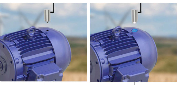
A UGV can discover uneven floor with the assistance of vibration sensors. Supply: ckybe, AI, by way of Adobe Inventory
Just a few years again, throughout a area trial, we had a midsized uncrewed floor automobile, or UGV, climbing what seemed like a innocent patch of damaged floor. Nothing excessive. Some free stones, a little bit of mud, slight incline. The type of terrain you wouldn’t assume twice about.
Midway up, the robotic hesitated. Then one wheel dropped barely, the chassis leaned ahead, and earlier than anybody may react, it tipped.
The unusual half? The digicam feed seemed positive. Lidar didn’t flag something critical both. On paper, the trail was “safe.”
However the robotic knew one thing was fallacious earlier than we did. It simply didn’t know act on it.
That hole between what the robotic sees and what it feels, is on the coronary heart of cell robotic stability and uneven terrain issues.
Out in the true world, terrain lies. A floor can look compact however behave like powder below load. Rocks disguise below skinny layers of soil. Even slight ruts can shift weight sufficient to push a UGV previous its stability margin. And as soon as that tipping level is crossed, restoration isn’t sleek.
Most navigation stacks at the moment are nonetheless closely vision-driven. Cameras, lidar, SLAM—they do an excellent job constructing maps. However they don’t let you know how the bottom will reply while you drive over it. That’s the place issues break.
Vibration monitoring modifications the method totally. As a substitute of relying solely on exterior notion, the robotic begins listening to its personal physique. Each bump, each micro-slip, each influence, it’s all knowledge. And while you begin treating these indicators severely, they grow to be predictive.
The closest analogy is an individual strolling on free gravel. You don’t analyze the terrain visually at each step. You are feeling it. Tiny shifts below your toes let you know when to decelerate, modify your stability, or change path.
That’s what we’re making an attempt to present robots.
What follows isn’t theory-heavy dialogue. That is based mostly on what truly works within the area, how vibration knowledge is captured, what it tells you, and flip it into one thing that retains your robotic upright when the bottom will get unpredictable.
Why vibration indicators matter for stability
Let’s begin with the essential query engineers usually ask: How do vibrations truly have an effect on stability?
Quick reply: They don’t simply have an effect on it; they reveal it.
Each time a wheel interacts with terrain, it generates a power. That power isn’t fixed. It modifications relying on whether or not the floor is difficult, gentle, uneven, or shifting. These modifications journey by way of the robotic as vibrations.
In the event you ignore them, they’re noise. In the event you analyze them, they’re insightful.
In one in all our off-road check runs, we drove the identical robotic throughout three surfaces: compact dust, free gravel, and gentle sand. Visually, all three seemed manageable. However the vibration profiles had been utterly completely different.
On compact dust, the sign was steady. Low amplitude, constant.
On gravel, it turned chaotic. Sharp spikes, high-frequency chatter.
On sand, every little thing slowed down. The sign turned heavier, nearly sluggish, with noticeable low-frequency oscillations. That distinction issues.
Excessive-frequency spikes normally imply impacts—rocks, particles, laborious edges. These are the moments that may out of the blue shift load distribution and set off instability.
Low-frequency oscillations are extra delicate however simply as harmful. They usually point out lack of help, like when a wheel begins sinking or slipping. You don’t get a sudden jolt. As a substitute, you get a gradual lack of stability.
Now right here’s the essential half: you usually really feel these results earlier than you see them.
We bumped into this throughout rover-style testing. A stretch of terrain seemed clean as a result of a skinny layer of sand coated embedded rocks. Cameras noticed flat floor. Lidar noticed a clear floor.
However the IMU informed a distinct story. As quickly because the wheels rolled over these hidden rocks, the vibration sign lit up with high-frequency spikes. That gave us an early warning—earlier than the robotic bodily destabilized.
That’s why vibration sensing is so highly effective. It doesn’t depend upon visibility. It doesn’t care about lighting or mud. It displays precise contact physics.
In tough environments, that’s usually the one reality that issues.

Core sensors for vibration monitoring
If vibration is the sign, sensors are your ears. And like every sensing system, placement and high quality matter greater than most individuals anticipate.
On the core, you’re working with three elements: accelerometers, gyroscopes, and inertial measurement models (IMUs).
Accelerometers do the heavy lifting. They measure linear acceleration alongside three axes, which suggests they seize each shocks and steady vibration. If a wheel hits a rock, the accelerometer sees it immediately. If the chassis begins oscillating, it reveals up there too.
Gyroscopes add one other layer. They monitor angular movement—roll, pitch, yaw. That is what tells you if the robotic is beginning to tilt or rotate in a approach that may result in tipping.
Mix the 2, and also you get an IMU. Most trendy methods depend on IMUs as a result of they offer you an entire image of movement.
However right here’s the place real-world expertise is available in: the place you mount these sensors issues as a lot because the sensors themselves.
Mounting an IMU on the middle of mass is customary apply, and for good cause. It offers you a steady reference for total movement. But when that’s all you employ, you’ll miss lots of element.
In tough terrain, a lot of the motion occurs on the wheels. We’ve had significantly better outcomes including secondary accelerometers nearer to the wheel assemblies. These choose up localized impacts that by no means totally propagate to the middle of the chassis.
One other mistake I’ve seen is gentle mounting. It sounds minor, but it surely’s not. In case your sensor mount flexes even barely, you’re now not measuring true vibration—you’re measuring a filtered model of it. That results in fallacious conclusions.
Sampling price is one other sensible consideration. For many cell robots, staying within the 100 to 500 Hz vary is sufficient. Go too low and also you miss crucial occasions. Go too excessive and also you’re simply including processing overhead with out a lot profit.
As for {hardware}, you don’t want unique elements. There are many dependable accelerometer sensors obtainable that may deal with harsh environments with out blowing your price range. What issues extra is calibration and consistency.
Actual-time vibration processing strategies
Uncooked vibration knowledge is messy. In the event you’ve ever plotted it straight from an IMU, you understand what I imply. It appears like noise.
The trick is to not clear it utterly, however to scrub it simply sufficient to disclose patterns.
Step one is filtering. Motors, gearboxes, and even structural resonance all introduce their very own vibrations. In the event you don’t take care of these, they’ll drown out terrain indicators.
We usually begin with a bandpass filter to isolate the frequency vary the place terrain interplay lives. Then, if there’s a identified noise supply like a motor spinning at a set frequency we drop in a notch filter to take away it.
I’ve seen circumstances the place a easy notch filter made the distinction between unusable knowledge and clear terrain signatures. As soon as the sign is usable, you progress into evaluation.
Time-domain evaluation offers you a way of how the sign evolves. However frequency-domain evaluation is the place issues get attention-grabbing. Utilizing FFT, you may see precisely the place vitality is concentrated.
Completely different terrains depart completely different fingerprints. Gravel spreads vitality throughout excessive frequencies. Grass sits someplace within the center. Sand shifts every little thing decrease and dampens it.
From there, you extract options. Not dozens — only a few significant ones. RMS amplitude, spectral energy, and possibly variance. That’s normally sufficient.
We as soon as constructed a easy terrain classifier utilizing only a handful of those options and obtained near 90% accuracy at low speeds. Nothing fancy. No deep studying. Simply clear knowledge and good function choice.
The important thing lesson? You don’t at all times want complicated fashions. You want good indicators.
Completely different strategies of connecting a three-axis vibration sensor. Supply: ATO
Stability prediction from vibration knowledge
That is the place issues get attention-grabbing. Most methods react to instability after it begins. By then, you’re already in hassle. What vibration monitoring permits you to do is shift from response to prediction.
Historically, engineers depend on metrics like stability margin or power distribution fashions. These work effectively in managed environments however battle when terrain habits modifications unpredictably.
Vibration knowledge fills that hole. As a substitute of estimating forces purely from fashions, you infer them from precise interplay. That makes your stability evaluation extra grounded in actuality.
Extra not too long ago, we’ve seen learning-based approaches take over this house. Feed acceleration, angular velocity, and velocity knowledge right into a mannequin, and it outputs a stability rating.
What’s spectacular is how effectively these fashions generalize.
In a single check, we skilled a mannequin on grass, gravel, and dust. Then we ran it on combined terrain it had by no means seen earlier than. It nonetheless carried out effectively. Not excellent, however adequate to be helpful.
In sensible phrases, this lets you do issues like gating habits.
We had a UGV with a small manipulator arm. When vibration ranges crossed a threshold, the system would pause arm motion mechanically. That alone prevented a number of near-tip incidents.
The essential factor right here isn’t the mannequin itself. It’s the concept stability turns into one thing you monitor constantly, not one thing you test after the actual fact.
Management methods for enhanced stability
When you belief your vibration knowledge, you can begin utilizing it in management. The only method is pace adaptation. And truthfully, it’s probably the most efficient. When vibration will increase, decelerate. That’s it.
It sounds primary, but it surely works as a result of most instability points scale with pace. Decrease pace means decrease dynamic forces, which supplies your system extra time to react.
Past that, you may feed vibration knowledge into your management loops. PID controllers, for instance, can profit from an extra enter that displays disturbance ranges. This helps cut back oscillations and improves response.
Sensor fusion additionally performs a task. Vibration knowledge alone is highly effective, however combining it with odometry or visible suggestions makes it much more dependable.
One sensible enchancment we noticed got here from cleansing up inside noise. By filtering out mechanical vibrations from inside elements, the management system turned noticeably smoother. Much less jitter, higher stability.
Generally stability enhancements don’t come from including complexity. They arrive from eradicating noise.
Implementation challenges and fixes
In fact, none of that is plug-and-play. Noise is the largest problem. Not all vibrations are helpful. Some come from motors, some from construction, some from the surroundings. The purpose is to separate sign from noise with out shedding essential data.
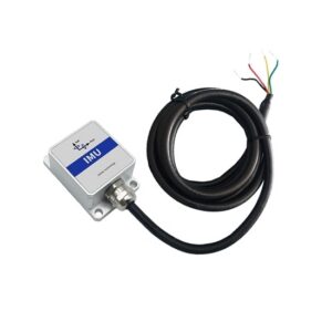
A small IMU sensor for robots and drones. Supply: ATO
Sensor drift is one other situation, particularly with gyroscopes. Over time, small errors construct up. That’s the place sensor fusion strategies like Kalman filtering grow to be important.
Then there’s variability. Change the robotic’s pace or payload, and your vibration profile modifications too. In case your system isn’t designed to deal with that, efficiency drops shortly.
The one actual answer right here is testing. Not managed lab testing actual terrain, actual circumstances, actual edge circumstances. That’s the place methods show themselves.
Robots must really feel the bottom
If there’s one takeaway from all of this, it’s easy: robots must really feel the bottom, not simply see it.
Cell robotic stability and uneven terrain challenges received’t be solved by higher maps alone. They require a deeper connection between the machine and its surroundings.
Vibration monitoring offers that connection. It turns impacts, slips, and delicate shifts into usable knowledge. It permits robots to anticipate issues as a substitute of reacting to them. And in environments the place a single mistake can finish a mission, that makes all of the distinction.
The expertise isn’t out of attain. A strong IMU setup, some considerate processing, and a little bit of area testing can take you a great distance. From there, it’s iteration.
As a result of the terrain will at all times shock you. The purpose is to verify your robotic isn’t shocked for lengthy.
 In regards to the writer
 In regards to the writer
Faisal Mahmood is a seasoned digital advertising and tech content material strategist with in depth expertise in AI, software program growth, and Website positioning-driven content material. He focuses on creating deeply researched, fact-based articles that assist builders, enterprises, and tech groups perceive the newest developments in AI-powered instruments, coding greatest practices, and safe software program growth.
Mahmood is captivated with bridging the hole between rising expertise and sensible insights for international audiences. He’s reachable at faisal@aidetector.professional.
The put up Enhancing cell robotic stability on uneven terrain by way of vibration monitoring strategies appeared first on The Robotic Report.