


Contract manufacturers like Magna International allow established automakers to delegate serial production, handle ramp-downs, and experiment with new vehicle concepts without straining their own manufacturing networks. For automotive startups, Magna can reduce risk by offering access to proven operations, experienced workers, and dependable supply chains.
Our facility in Graz houses a body-in-white (BIW) assembly line, a paint shop, and final assembly operations. The plant is tailored for low-volume vehicle programs. It can accommodate all powertrain technologies on one assembly line while distributing production loads evenly across different models.
A multi-product BIW assembly line comprises several key elements, including the vehicle underbody, a TPD, and fixed jigs. Illustration courtesy Magna International
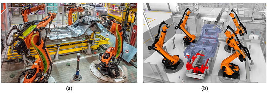
These images depict our inline measurement station used for inspecting BIW assemblies. The four six-axis robots are fitted with optical metrology sensors. The 3D model (right) highlights the underbody in blue and the TPD in red. Photo courtesy Magna International
Contract manufacturing introduces distinct technological hurdles, especially when multiple vehicle variants share the same assembly line.
To guarantee dimensional precision and structural integrity of a BIW, the underbody’s position on the line must be held accurately and consistently at every step. This is essential for welding, fastening, and inspection tasks. Typically, this is accomplished by geometrically aligning and clamping the underbody to fixed jigs using central mounting points.
However, when different model variants are built on the same line, an extra component is required: transportable positioning devices (TPDs). These act as adapters that accommodate diverse underbodies within a standardized mounting and clamping framework, preserving geometric alignment at each station. Once inside the body shop, each underbody is paired with a dedicated TPD, which travels with it through the entire BIW process until it is transferred to the paint shop.
The positioning devices are methodically cycled through the line. Spare units are kept in storage and fed back into production as needed. Our Graz factory can run up to 50 TPDs concurrently for each product, depending on the model mix and production volume.
Geometric inaccuracies in the TPDs—caused by wear over time—directly translate into defects in the vehicle structure. Such defects can lead to quality-related expenses, including scrap and rework. The challenge is made worse by the fact that the locators used to geometrically align the underbody on the TPD cannot be measured during active production. Instead, the TPDs must be removed from the line at regular intervals for inspection and upkeep, which is both expensive and disruptive.
Looking for quick answers on assembly and manufacturing topics?
Try Ask ASM, our new smart AI search tool.
Ask ASM
To address this issue, we engineered a cyber-physical inspection system designed to detect and reject TPDs that fall outside specifications. We built a system that maps the cause-and-effect geometric relationships between TPDs and vehicle bodies, allowing us to infer deviations from measurement data through “big data” analytics.
Not stopping there, we leveraged that knowledge to create a cyber-physical assembly system that allows us to configure advanced, flexible TPDs on demand.
The BIW Manufacturing Process
BIW manufacturing follows a step-by-step sequence. Sheet metal components and pre-assemblies are joined into subgroups, which are then fitted onto the underbody. Once assigned to a TPD, the underbody moves through fully automated framing and welding stations. Side panels are attached using mechanical joining techniques. Doors and closures are installed. Finally, surface finishing is completed before the body is handed over to the paint shop.
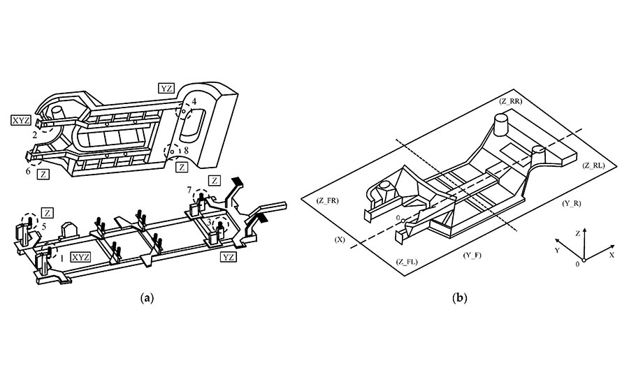
Four holes in the underbody align with four locating pins on a TPD. Illustration courtesy Magna International
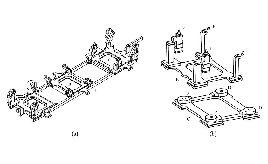
Magna’s FTPD is composed of several components. The left drawing shows the main frame (A) with three docking modules (B). The right drawings depict a docking module, which includes a main module (C) with four locking mechanisms (D); and a swappable docking plate (E) with four receptacles (F). Illustration courtesy Magna International
Assembly sequencing and component identification are overseen by a manufacturing execution system (MES). Tracking is managed directly by the PLC, as well as through bar codes or RFID tags.
Traditionally, geometric quality control is performed by removing small samples of subassemblies and finished bodies from the line for inspection on coordinate measurement machines (CMMs). Based on those measurements, process adjustments are identified, carried out, verified, and recorded.
However, assembly defects attributable to individual TPDs cannot be reliably caught through sampling, since their likelihood of occurrence is too low relative to the sample size. As a result, TPD inspection and maintenance must be conducted on a fixed schedule.
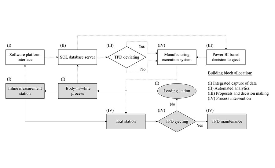
This diagram outlines our cyber-physical inspection workflow. Physical components appear in gray, while computational components are in white. Decision points throughout the flow help distinguish between conforming and non-conforming TPDs. Illustration courtesy Magna International
The Flexible Positioning Approach
To address the challenge, we deployed three robot-driven optical inline measurement stations across the BIW line. Our objectives were to speed up process stabilization, tighten process control, guarantee quality documentation, and cut down on scrap, rework, and unplanned downtime.
Positioned at strategic points along the production flow, each station relies on four robots fitted with precision optical sensors for image processing, line triangulation, and shadow analysis—collectively tracking roughly 100 critical features. Every feature takes between 3 and 4 seconds to measure. Measurement precision reaches ±0.25 millimeter when correlated to coordinate systems, ±0.2 millimeter for static tests, and ±0.3 millimeter for dynamic process evaluations.
The stations feature advanced compensation mechanisms to sustain metrological reliability over time. Each station uses calibration artifacts to counteract robot-generated thermal drift and to support automated recalibration cycles. These built-in compensation routines are further reinforced by periodic external verification, including correlation comparisons against CMM measurements.
Four holes on an underbody align with four locating pins on a TPD. Any misalignment in a TPD can therefore shift the underbody’s position along the X, Y, or Z axis.
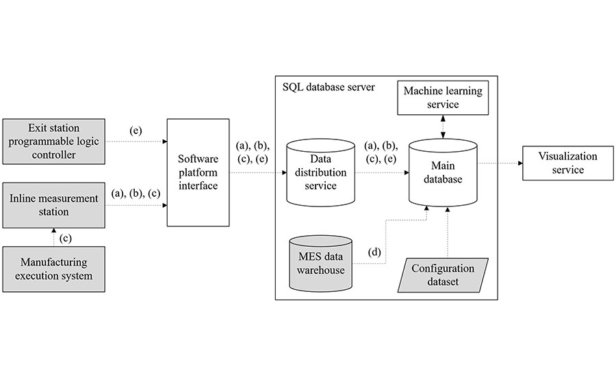
This diagram traces the data our system gathers, where it travels, and how it gets processed. Illustration courtesy Magna International
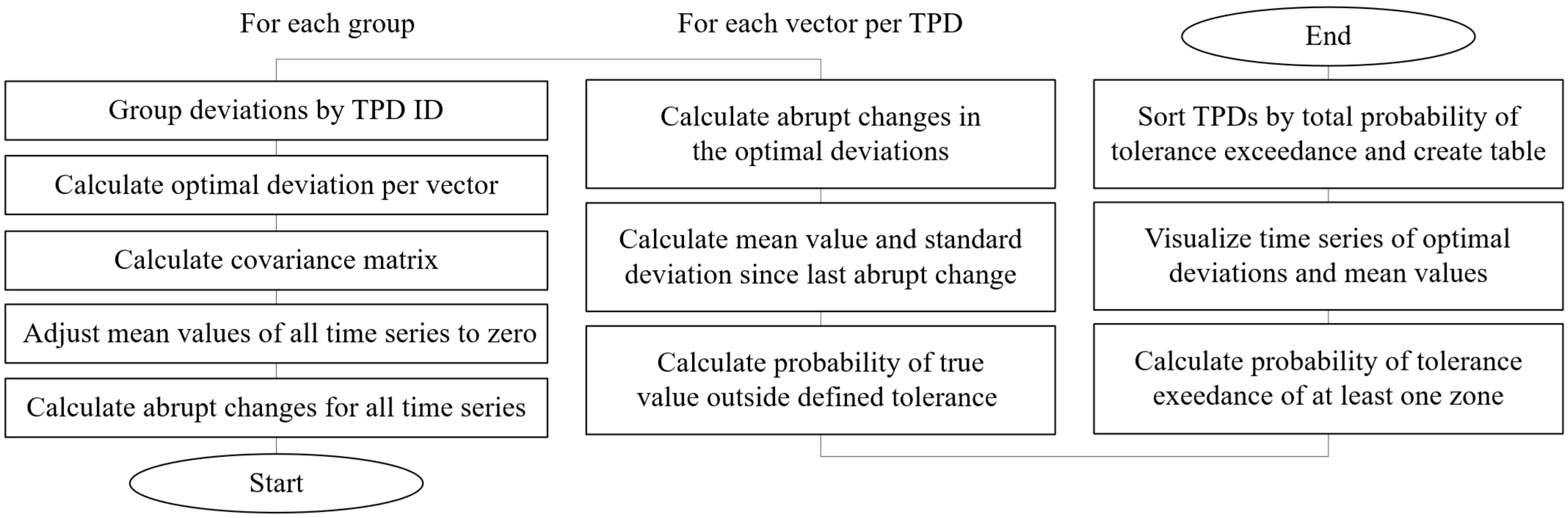
This flowchart lays out the programming logic for evaluating TPD data. Every block corresponds to a specific algorithmic step. Illustration courtesy Magna International
Our conventional TPD concept demands significant customization for each new product variant. Additionally, since the TPDs come from an external supplier, a fixed quantity must be ordered based on projected production volumes. Consequently, there is minimal flexibility to adjust for shifts in unit demand or alterations to the production schedule over the lifespan of a multiyear program.
To boost both efficiency and adaptability, we engineered a next-generation TPD. Our flexible transportation positioning device (FTPD) allows rapid, model-specific reconfiguration directly within the BIW manufacturing workflow. It accommodates different vehicle types seamlessly through interchangeable docking plates fitted with variant-specific receptacles.
At the heart of the system sits a rigid frame designed to house multiple modules. Each module delivers a precise mechanical interface for securing interchangeable docking plates. The docking plates carry bearing surfaces, consoles, and tensioning components that accurately position, mount, and clamp various underbody models relative to the vehicle coordinate system.
The docking plates are flat, plate-like elements that can be attached to a main module either manually or via automated handling systems. For exact positioning, each docking plate features retractable clamping bolts on its underside that extend vertically downward. These bolts lock into matching zero-point clamping and locking mechanisms—also referred to as quick-change pallet systems—which are built into the main module, guaranteeing repeatable positioning within established tolerance ranges.
The main modules include integrated media interfaces that deliver compressed air, electrical power, and signal connectivity. Once the bolts engage pneumatically, the docking plate and the main module—anchored to the main frame—form a mechanically rigid, precision-aligned docking assembly.
The architecture permits a single main module to work with multiple docking plates. Different docking plates carrying variant-specific receptacles can be swapped in with precision, requiring no alteration to the main frame or main modules. This makes it possible to manufacture different vehicles using the same core equipment.
The device comprises at least three main modules and three interchangeable docking plates—one plate per module. To reconfigure the FTPD for a new model variant, only the clamped docking plates need to be replaced. The main frame and main modules stay in place, dramatically cutting changeover time and upfront investment. The design also mitigates quality problems that arise from geometric wear in TPDs over extended use.
Our FTPDs comply with ISO 14638, ISO 5459, and ISO 1101 standards, and they hold a geometrical fixture deviation tolerance of ±0.2 millimeter—matching the precision of our original TPD design.
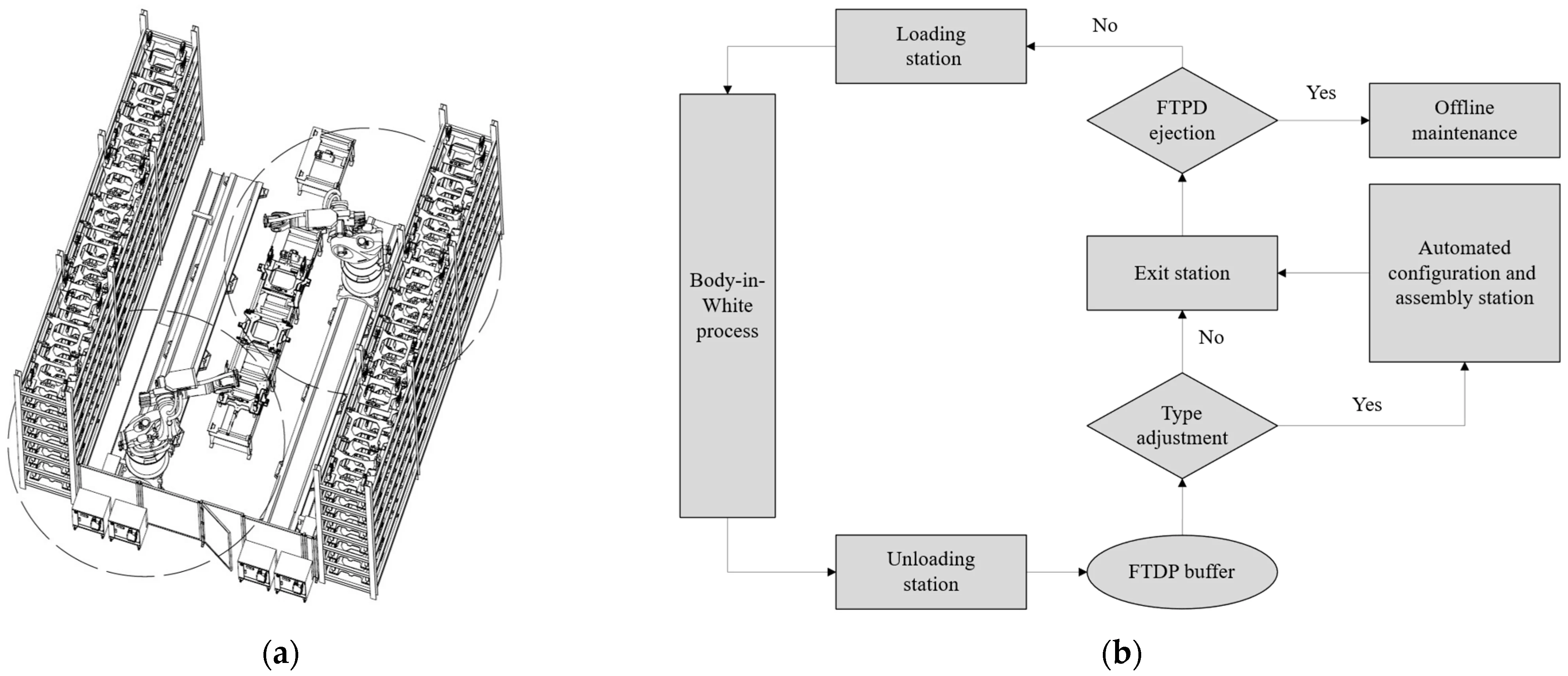
The drawing on the left depicts our automated configuration and assembly station for FTPDs, with circles indicating each robot’s range. The flowchart on the right presents the decision tree for a typical BIW assembly process. Illustration courtesy Magna International
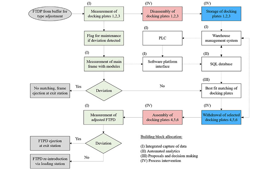
This station flowchart illustrates the replacement of an entire docking plate set—switching from plates 1 through 3 to plates 4 through 6. External elements appear in gray, measurement elements in green, handling elements in red, warehouse elements in blue, and simplified computational elements in white. Illustration courtesy Magna International
Cyber-Physical Inspection System
We built a cyber-physical inspection system to flag TPDs that fall outside specifications. Sensor data is captured, processed, and fed back to actuators and digital interfaces. Specifically, the system gathers five categories of data: assembly measurements, production timestamps, unique identifiers for each assembly, unique identifiers for each TPD, and maintenance timestamps.
Product configuration data is also integrated and made available to a machine learning service, which executes a Python 3.10 script each day before the first shift begins. Visualization is handled through Microsoft Power BI, with daily updates delivered by an on-premises report server. Data exceeding 36 months in age is archived on a monthly basis.
A Python script within the machine learning service identifies deviating TPDs based on incoming data inputs and
Extended monitoring confirms that outside variables—such as variations in material batches or shifts in environmental conditions—had no impact on the outcomes. The algorithm’s accuracy was confirmed by ejecting TPDs that fell outside specifications and then cross-checking the associated deviations using coordinate measuring machine (CMM) verification.
TPDs that do not meet specifications are flagged by the MES, detected by the RFID reader, and physically removed from the line by the exit station’s PLC so they can be serviced offline.
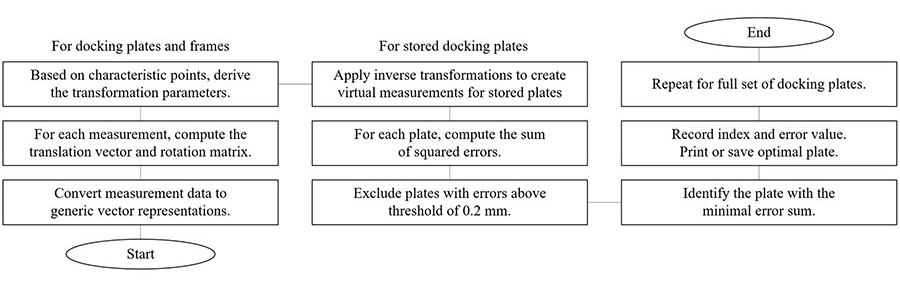
This flowchart illustrates the programming workflow for reconfiguring FTPDs. Photo courtesy Magna International
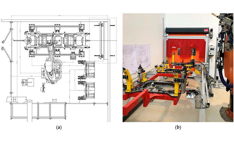
This illustration and photograph depict our fixture setup used for reconfiguring FTPDs. Photo courtesy Magna International
Cyber-Physical Assembly System
The on-demand configuration and assembly of FTPDs revolves around a parts storage magazine built from swappable docking plates, each designed for a particular product variant. The central workflow consists of picking the right docking plates and pairing them precisely with universal main frames, with the goal of keeping tolerance stack-ups between mating components as small as possible.
The warehouse management system handles plate selection, drawing on measurement data captured by an automated optical inspection system. Docking plates mounted on arriving FTPDs are measured first. Once the plates are removed, the main modules fixed to the main frames are measured as well. A matching algorithm then determines which docking plate set offers the best fit for the given main frame. From that point onward, both disassembly and reassembly of the FTPDs are carried out automatically by robotic systems.
Following configuration and assembly, each FTPD undergoes a final measurement step to confirm it meets all required specifications.
Configuring the FTPDs requires seven distinct categories of data: docking plate measurements, main module measurements, post-configuration FTPD measurements, warehouse storage location, the FTPD’s unique identifier, a timestamp, and a cycle counter.
The best-fit matching algorithm is designed to offset deviations present in individual components by choosing the combination of modules and docking plates that yields the most favorable overall tolerance. The allowable geometric deviation for any single part is set at ±0.1 millimeter, whereas the tolerance for the fully assembled combination is set at ±0.2 millimeter.
FTPDs are routed into the configuration and assembly station based on instructions issued by the MES.
Results
Our cyber-physical inspection system delivered meaningful reductions in time, labor, and cost; however, exact figures are not reported in this paper due to confidentiality agreements.
Our cyber-physical assembly system has passed prototype validation and is ready for procurement. A complete system installation and pilot rollout are scheduled for the upcoming customer project. The FTPD design—together with the patented configuration process and best-fit matching approach—proved to be robust and well-suited for high-volume production environments.
Editor’s note: This article summarizes a research paper co-authored by Christoph Kribernegg, project leader for body-in-white at Magna International; Stefan Koerner, research associate at Know Center Research GmbH, Graz; and Martin Schellander and Franz Haas, research associates at Graz University of Technology. To read the full paper, click here.