



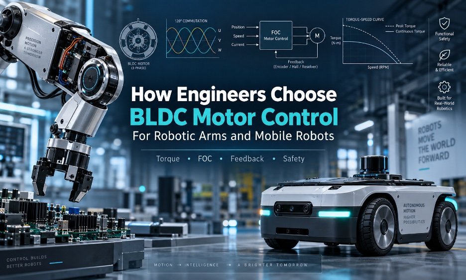
# How to Choose the Right Brushless DC Motor for Your Robot
## Introduction
Building a robot — whether it’s a robotic arm on a factory floor or a mobile robot navigating a warehouse — means making one of the most important decisions early in the design process: choosing the right electric motor. The brushless DC motor, commonly known as a BLDC motor, is the go-to choice for modern robots. It’s efficient, reliable, and offers excellent performance. But picking the correct one isn’t as simple as looking at a catalog and choosing the motor with the right voltage label.
A BLDC motor is really just one piece of a much larger system. The drive electronics, sensors, gears, brakes, wiring, software, and even the battery all work together to determine whether the motor performs well in the real world. Get any one of these pieces wrong, and the entire robot can suffer.
This guide breaks down the key factors engineers need to consider when selecting a BLDC motor for robotic arms and mobile robots — from understanding the mechanical loads all the way through to testing and commissioning.
—
## Start With What the Motor Needs to Do
Before looking at any motor or controller, the first step is understanding the job. What does the robot need to accomplish? This means mapping out the full mechanical load — the forces, speeds, torques, and movements the motor will be asked to handle during operation.
For a robotic arm joint, the key questions are:
– How much torque is needed to move the arm and its payload?
– Does the joint need to hold position under load (holding torque)?
– What speeds are required, and how quickly does the arm need to accelerate and decelerate?
– How often will the motor be running continuously versus in short bursts?
For a mobile robot, the focus shifts:
– How heavy is the robot, and what terrain will it encounter?
– What are the rolling resistance and slope conditions?
– How much starting torque is needed to get the wheels moving?
– Will the robot recover energy during braking or downhill travel?
A few basic equations help frame the problem. Torque at the joint equals the motor torque multiplied by the gear ratio and gearbox efficiency, minus any mechanical losses. Speed at the motor is simply the joint speed multiplied by the gear ratio. And electrical power drawn from the battery is roughly the mechanical power divided by the total system efficiency.
These calculations don’t replace a detailed simulation, but they give engineers a solid starting point and help identify which parameters truly matter before a controller is even selected.
—
## Understanding Commutation: Six-Step, Sinusoidal, and Field-Oriented Control
Once the mechanical requirements are clear, the next decision is how to control the motor. BLDC motors come in two main varieties based on their back EMF waveform: trapezoidal and sinusoidal. Each works best with a different control strategy.
**Six-step commutation** (also called trapezoidal commutation) is the simpler approach. It switches power through the motor’s three phases in six discrete steps based on rotor position. This method is straightforward to implement and works well with basic Hall effect sensors. It’s a great fit for applications where cost matters and the motor mainly runs at moderate to high speeds where fine torque control isn’t critical.
**Sinusoidal commutation** drives the motor phases with smoothly varying current signals instead of discrete steps. This reduces torque ripple and makes the motor run more quietly and smoothly, which matters for robots that need gentle, precise movements.
**Field-oriented control (FOC)** is the most advanced approach. It uses mathematical transformations to break the motor’s electrical signals into two independent components — one for torque and one for magnetic flux. This allows the controller to regulate torque directly and respond quickly to changing conditions. FOC is ideal for applications that demand smooth low-speed motion, fast torque response, and precise speed regulation, such as collaborative robot joints or high-performance mobile platforms.
However, FOC doesn’t automatically guarantee precision. The quality of the rotor position feedback, the accuracy of current sensing, the tuning of the control loops, and the condition of the mechanical transmission all play a role. A sophisticated algorithm can’t compensate for a poorly aligned encoder or a sloppy gearbox.
—
## Choosing the Right Feedback System
Feedback is how the motor “knows” where it is and how fast it’s spinning. Selecting the right feedback method is just as important as choosing the control strategy.
– **Hall effect sensors** are simple, inexpensive, and provide basic rotor position information. They work well for six-step commutation and simple speed control but lack the resolution needed for precise positioning.
– **Incremental encoders** provide much more detailed position information and are widely used in servo applications. They track movement but need a reference point at startup.
– **Absolute encoders** provide a unique position value at any moment, including right after power-up. This eliminates the need for a homing sequence, which is valuable in applications where the robot needs to be operational immediately.
– **Optical encoders** offer high resolution but need protection from dust, moisture, and vibration. **Magnetic encoders** are more compact and tolerate contamination better. **Resolvers** are built for harsh environments and high reliability.
Where the sensor is placed matters too. A sensor mounted on the motor shaft tells you the motor’s position, but not necessarily the output shaft’s true position — especially if there’s a gearbox involved. Gear backlash, compliance, and mechanical stretch can all introduce errors. In some cases, placing a second sensor on the output side of the transmission provides a more accurate picture of the actual joint or wheel position.
For cost-sensitive designs, **sensorless control** eliminates physical position sensors entirely by estimating rotor position from the motor’s back EMF signal. This reduces wiring and simplifies packaging but can struggle during startup and at very low speeds.
—
## Matching the Motor to Robotic Arms
Robotic arms have unique demands. Joints need to produce controlled torque at low speeds, hold precise positions, respond quickly to collisions, and sometimes be backdrivable (meaning a person can manually move the arm without damage). Thermal performance is also critical because a robotic arm may hold a position for long periods, generating heat in the motor and gearbox.
A basic robotic arm joint might use a BLDC motor with Hall sensors and an external controller for straightforward speed or position control. This architecture is simple to set up and maintain.
More demanding applications typically use an encoder-based FOC servo drive that runs a fast current loop internally, with velocity and position loops managed at a higher level. This architecture enables precise torque control and supports advanced behaviors like impedance control and collision detection. However, commissioning becomes more involved — every loop from current to velocity to position needs careful tuning.
An **integrated actuator** combines the motor, gearbox, encoder, drive electronics, brake, temperature sensor, and communication port into a single unit. This approach reduces wiring, saves space, and simplifies integration. The trade-off is less visibility into the internal components and potential dependence on the manufacturer for maintenance and replacement.
Key selection criteria for robotic arms include peak torque at every joint, holding torque at zero speed, brake requirements, backdrivability, torque estimation accuracy, gearbox efficiency, and how the system handles emergency stops.
—
## Matching the Motor to Mobile Robots
Mobile robots place different demands on their motors. The wheels are the interface between the robot and the world, so traction, braking, and speed regulation take priority.
For a **differential-drive autonomous mobile robot**, the two drive wheels need to track commanded velocities accurately. Wheel speed feedback also feeds directly into the robot’s odometry system, so encoder resolution matters for localization and docking accuracy. Hall sensors alone may not provide enough information for precise navigation.
**Four-wheeled platforms** add complexity because all wheels need to work in harmony. Wheel speed mismatches, mechanical loading differences, and wheel slip can all degrade performance. **Outdoor unmanned ground vehicles** face even greater challenges — dust, water, temperature extremes, rough terrain, and long periods of sustained operation all push the system harder.
Battery behavior plays a significant role in motor selection. Voltage sags during acceleration reduce the available power, while regenerative braking during deceleration can spike the voltage on the DC bus. A controller that’s rated for a nominal battery voltage needs to perform reliably across the battery’s full operating range.
Thermal management is another critical factor. A drive unit tucked inside a wheel or compact chassis may have very little airflow, meaning heat has to be managed through careful thermal design of the entire assembly.
—
## Evaluating Current Ratings and Thermal Performance
Motor and controller current ratings are easy to misunderstand. A datasheet might list continuous phase current, continuous bus current, peak phase current, peak duration, RMS current, or configurable current limits. These numbers are not interchangeable.
The motor’s thermal limit, the inverter’s semiconductor ratings, connector ratings, cable ratings, and battery capability can all be lower than the headline peak current number. A controller marketed with a large peak current specification is not automatically suitable for a motor that requires that level of current continuously.
Understanding the heat path is essential. Motor winding losses dissipate heat through the motor’s structure and mounting. Power stage losses in the inverter must be carried away through the enclosure, heat sink, and airflow. Testing under realistic operating conditions — the actual duty cycle, not just a short unloaded bench test — gives a much clearer picture of how the system will perform in the real world.
—
## Communications, Software, and Safety
Modern robots rely on digital communication networks to coordinate their many components. When selecting a BLDC motor controller, engineers should check for support of protocols like CAN, CANopen, EtherCAT, RS 485, and UART. Encoder interface compatibility, feedback update rates, command latency, and fault reporting are all important.
Standards like **CANopen’s CiA 402** profile provide a common framework for servo drives, making it easier to mix and match components from different manufacturers. **EtherCAT** becomes especially valuable when multiple axes need synchronized motion with deterministic timing.
Software integration matters too. Frameworks like **ROS 2** (Robot Operating System 2) provide a standard way to connect robot controllers to physical actuators. But communication support alone doesn’t guarantee real-time performance — the control loop execution timing must also be verified.
Safety should be treated as a system-level architecture, not a single feature to check off a list. A motor controller with an overcurrent shutdown is not the same as a certified safety function. Engineers should look for protection against overcurrent, short circuits, overvoltage, undervoltage, overtemperature, overspeed, encoder failure, phase loss, stall conditions, and emergency stop behavior. Relevant standards like ISO 10218, ISO 13849, and IEC 61800 address safety requirements for industrial robots and adjustable speed drive systems. The safety function needs to be designed, validated, and integrated into the overall system.
—
## A Practical Selection Process
Following a structured process helps ensure nothing gets overlooked. Here’s a step-by-step workflow:
1. Define the complete load and motion profile, including acceleration, deceleration, payload, terrain, gravity, and duty cycle.
2. Calculate continuous and peak torque at the motor shaft and at the joint or wheel.
3. Establish the required speed range, acceleration profile, and any regenerative braking conditions.
4. Define the primary control objective: speed, torque, position, impedance, or traction.
5. Select the feedback type based on the control objective and mechanical transmission.
6. Choose the commutation strategy — six-step, sinusoidal, or FOC — based on motion quality and implementation constraints.
7. Verify voltage, current, regeneration, thermal margins, and battery behavior.
8. Select the communication and software interfaces needed by the robot architecture.
9. Define safety behavior, fault response, braking strategy, and restart conditions.
10. Validate the complete system — motor, drive, gearbox, sensor, brake, and robot controller — under realistic operating conditions.
—
## Frequently Asked Questions
**Q: Can I just pick a BLDC motor based on its wattage rating?**
A: Wattage alone tells you very little. The same wattage motor can behave very differently depending on its torque curve, speed range, thermal capacity, and the control system it’s paired with. Always compare the full specification set, including torque, speed, current, and duty cycle.
**Q: What’s the difference between a BLDC motor and a PMSM?**
A: In commercial robotics, the terms are often used interchangeably. Both are three-phase, permanent-magnet machines driven by electronic inverters. The difference lies in the back EMF waveform and winding design, which affects how the motor behaves with different control strategies.
**Q: Do I need encoder feedback if I’m using Hall sensors?**
A: It depends on the application. Hall sensors are sufficient for basic speed control and six-step commutation. If you need precise position control, smooth low-speed torque, or high-resolution speed regulation, an encoder — incremental or absolute — is typically necessary.
**Q: What is regenerative braking, and why does it matter?**
A: During deceleration or downhill travel, the motor acts as a generator and sends energy back to the power bus. This can be beneficial for energy recovery but can also cause over-voltage issues if the battery, controller, and braking circuit aren’t designed to handle it.
**Q: Is sensorless control a good choice for robots?**
A: It can be, particularly for applications where the motor spends most of its time at higher speeds. The main limitation is that back EMF-based estimation becomes unreliable at zero and very low speeds, so startup and low-speed operation need a careful strategy.
**Q: How important is EtherCAT or CANopen for a small robot?**
A: For simple robots with a single controller and a few motors, a basic serial or CAN connection may be sufficient. EtherCAT and CANopen become increasingly valuable as the robot scales up, with multiple axes that need synchronized, deterministic communication.
—
## Conclusion
Selecting a BLDC motor for a robot is a system-level decision, not just a motor selection. The right choice depends on balancing the mechanical load, the control strategy, the feedback architecture, the thermal environment, the power system, the communication protocol, and the safety requirements.
A simple indoor mobile robot might do well with a sensored six-step controller — affordable, robust, and easy to implement. A collaborative robot arm with demanding precision requirements will likely need encoder-based FOC with nested control loops and output-side feedback. An outdoor unmanned vehicle will need traction control, regenerative energy management, and environmental protection that an indoor robot simply doesn’t require.
The most important question isn’t which controller has the right voltage or wattage on its spec sheet. The real question is whether the complete system — motor, inverter, feedback, transmission, battery, software, and safety architecture — can deliver the required performance throughout the robot’s full operating range.
By following a structured selection process and validating the complete system under realistic conditions, engineers can make confident motor choices that lead to reliable, high-performing robots.
Thank you for reading
